Illustrated understanding of the basic components and parts of automotive engines
2025-04-11 10:38:10 hits:0
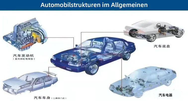
Engine (ENG)
Crank connecting rod mechanism -
1. Body group - (crankcase, cylinder head, cylinder gasket, cylinder block, oil pan, cylinder head cover, main bearing cover, feet);
2. Piston connecting rod group - (piston, piston ring, piston pin, connecting rod, connecting rod axle shaft shingle, connecting rod shingle cover, connecting rod bolts);
3. Crank flywheel group - (crankshaft, torsional shock absorber, main bearings, balance shaft, flywheel , crankshaft pulley, timing gear).
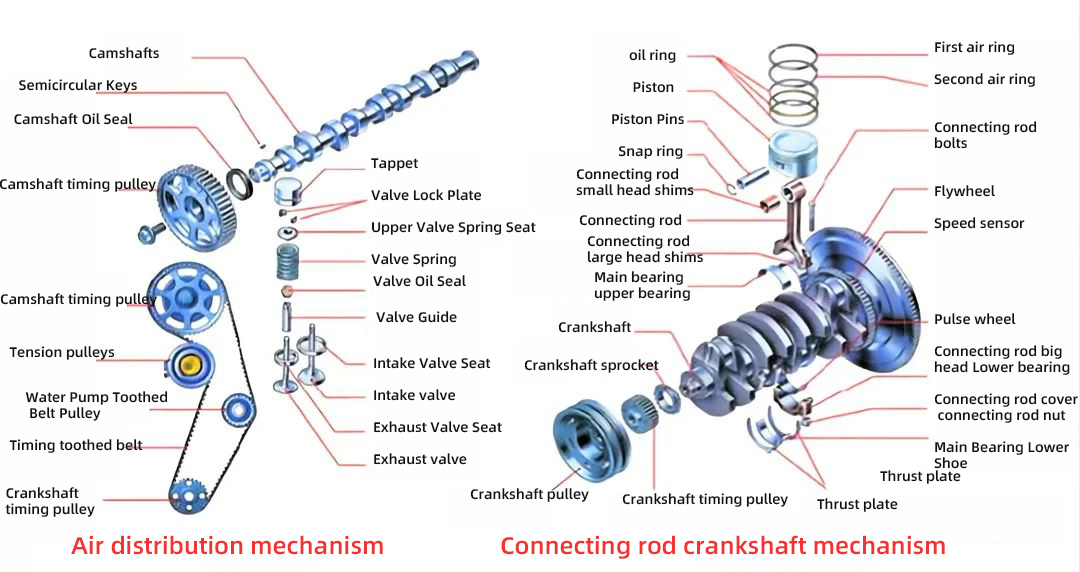
Valve train
(valve, valve guide, valve oil seal, valve spring, valve spring seat, valve locking clip); 2. Valve drive train - (timing sprocket, timing chain, chain tensioner and chain guide); 3. Valve timing train - (camshaft, valve tappet, valve top cup, valve rocker arm, rocker arm shaft, camshaft timing gear, valve pushrods); 4. Gas distribution phasing - (intake advance angle, intake lag angle, exhaust advance angle, exhaust lag angle, valve overlap angle).

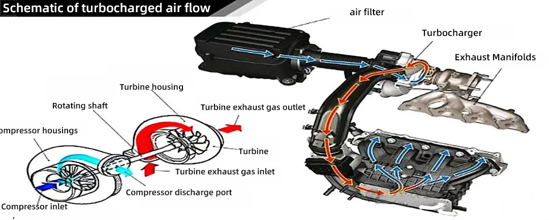
Intake system
Naturally aspirated, turbocharged, throttle, throttle position sensor (TPS), stabilizer chamber, throttle air filter, intake control valve, intake manifold, intake hose, intake manifold, vacuum control solenoid, intercooler, rest speed control valve, air flow meter (MAP), intake air temperature sensor, intake air pressure sensor, air flow sensor ( MAF), intake manifold and variable valve lift system.
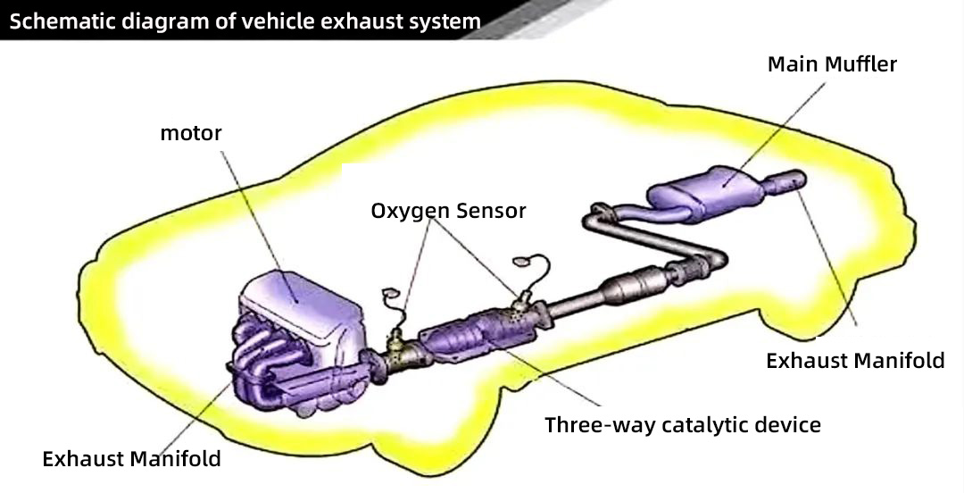
Emission system
Exhaust manifold, front oxygen sensor or A/F sensor, three-way catalytic converter (TWC), rear oxygen sensor, particulate trap (GPF), muffler, suspension, secondary air injection system, EGR valve (exhaust gas recirculation) and other components.
Cooling System
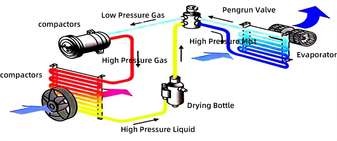
Water \ air-cooled, forced circulation water-cooling system, water pump, radiator (water tank), expansion tank (secondary water jug), cooling water pipe, coolant, thermostat, water temperature sensor, cooling cooling cooling fan, liquid level sensor, water temperature warning light, compressor, condenser, evaporator box, drying bottle, expansion valve, damper motor, blower fan, heater water valve and water temperature gauge.
Lubrication system
Oil, oil pump, oil filter, filter collector, radiator, PCV valve (crankshaft ventilation system), oil pan, oil compartment, main oil duct, oil cooler, oil pressure sensor, oil temperature gauge, oil dipstick, oil level and oil quality sensors, lubrication parts (e.g., connecting rods for the field axle, pistons, cam timing mechanism).
Starting system
Battery, starter, alternator.
Ignition system
Battery, alternator, ignition coil, disconnector, distributor, high voltage wires, ignition control module (ICM), spark plugs.
Fuel System
Fuel Tank, Electric Fuel Pump, Fuel Filter, Fuel Supply Rack (Fuel Distributor, Fuel Rails) Fuel Distribution Pipe, Injectors, Pulse Reducer (Fuel Pulse Damper), Fuel Injectors, Fuel Pressure Regulator, Fuel Vapor Recovery (EVAP), Electronic Control Unit, Actuators, RPM & Phase and Special Condition Control.
Air-conditioning system
air-conditioning compressor, condenser, evaporator, throttling and depressurizing elements (orifice tube or expansion valve), pressure switches, maintenance and testing joints, air-conditioning compartment, etc., liquid storage dryer (filter collector or desiccant).

 en
en  fra
fra  de
de  ru
ru  gle
gle  th
th  ara
ara  it
it  jp
jp  kor
kor  zh
zh 


